The following text is largely paraphrased
and/or exerpted from the RCN Publication Machinery
Digest for Destroyer Escorts, 205, 206, 257 and Classes. It should be noted, however, that this
document does not make mention whatsoever of the failure of the
automatic clutch and resulting removal of the cruise turbines, and this
information has been obtained from other sources - primarily from the article by David Bowie.
General
Layout and Description
|
| A
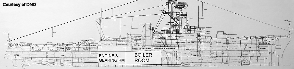
cross section of a RESTIGOUCHE class destroyer, showing the location of
the Boiler Room and the Engine and Gearing Room. Image courtesy of LCDR
Roger Heimpel, CFNES Damage Control Division. |
Y100
powerplants were installed in a large number of ships in the Royal and
Royal
Canadian Navies in the 1950s and 1960s, including the RN's Type 12 and
Type 14 frigates, as well as the Cadillacs (ST. LAURENT, RESTIGOUCHE,
MACKENZIE,
and ANNAPOLIS class destroyers) of the Royal Canadian Navy. The Y100
plant consisted of two boilers in a single
boiler room forward, with two geared turbines in a single engine room aft. The
reduction
gearboxes were installed in the engine room, just aft of each
turbine. The boiler and engine rooms were separated by a watertight
bulkhead. The RN's Type 12 frigates were arranged similarly to the RCN
ships, while the Type 14 frigates only had a single propeller shaft,
and therefore only had a single turbine and reduction gear set. HMCS
ST. LAURENT received an RN type Y100 powerplant with English Electric
turbines (as supplied by Yarrows Ltd), while the rest of the Canadian
ships received a slightly modified powerplant (manufactured in Canada)
with Parsons turbines and a different gearbox.
The main propulsion machinery, as designed, consisted of a cruise
turbine and a main turbine set, of which RCN destroyers had two of
each.
From between 5% and 30% of full power, the more efficient cruise
turbine was connected through the gearbox and provided all forward
propulsion. Above 30% of full power, the Napier automatic clutch system
disengaged the cruise turbine and engaged the main turbine to provide
up to and including 100% of full power. The astern turbine was
incorporated at the exhaust end of the main turbine casing. The
two stage main condenser was slung underneath the main turbine.
Power was transferred from the main gearbox to the propeller shaft by
the double reduction gearbox. Power from the cruise turbine was
transmitted to the main turbine drive gear via the Napier automatic
clutch and
an additional reduction gear. Both the cruise and main turbines were
controlled by a single ahead
throttle wheel, and the Napier clutch would automatically disengage at
30% power to allow the main turbine to take up the load.
Power was transmitted to the hull by the gearbox, which had its own
integral thrust block.
Boilers
The boiler room was situated athwartships and contained two Babcock and
Wilcox natural circulation, single furnace boilers (integral furnace,
with superheat control) located side-by-side and each with its own
uptake merged into a single funnel; the nine ships that received the
DDH conversion received twin funnels to allow for the installation of a
hangar. Each boiler was of the two-drum, bent-tube type, fitted with
double casings, and worked in an open boiler room. The double air-tight
casings were of stainless steel, between which the combustion air was
led to the burner registers.
Each boiler operated at 550 lb/sq.in. and 850 deg.F, and heat from fuel
combustion was transferred to the feed water in four ways:
- The heat of combustion of fuel in the furnace was
transferred by radiation and conduction to the waterwalls of the
furnace and the three rows of firerow tubes;
- By convection and conduction to the generator tubes
known as the convection bank;
- By conduction and radiation to the steam in the five
pass superheater;
- By conduction from the furnace gases that passed the
regulating dampers, to heat the feed water in the economizer.
Each boiler was totally enclosed with its own forced draught and
ducting, and the boiler room itself was kept largely at atmospheric
pressure. There was a cross-over connection between the forced draught
blowers, in the form of a hand-operated damper fitted between the
boiler casings of the two boilers, such that either blower could
provide air to both boilers (in case of failure of one blower) under
cruise and emergency conditions.
Boiler control was automatic to control steam temperatures and drum
level, with remote or manual control also provided. All other aspects
of boiler operation were manually controlled. A console was fitted just
aft of the boilers that incorporated the automatic and manual controls
and all indicators required for operation of the boilers.
A periscope type fitting was installed near the boiler room panel so
that smoke conditions could be observed.
Engines
Each engine originally consisted of main and cruise turbines (with the
cruise turbine mounted separately outboard of the main turbine) and a
set of single helical, double reduction gearing (i.e. the gearbox).
Each engine was installed side-by-side in a single engine room. As will
be discussed below, the cruise turbines were later removed or not
installed in
most ships. According to George Webster and Ron Monette, HMCS ST.
LAURENT retained the cruise turbines at least for a while.
From George Webster: "To start with,
the cruise turbines were fitted to one ship that I have personally seen
and that was HMCS St. Laurent. Apparently the clutch arrangement
was poorly designed and the cruise engine was rarely used. The
cruise turbines were indeed fitted outboard of the main engines and in
the remaining ships of this type (Y-100 machinery), there is a wider
than normal platform out board of the ahead main turbine where the
cruise turbine was originally supposed to have been fitted. I
can't recall how many cruise turbines were actually fitted but they
were all removed shortly after their introduction."
The main turbine drive was transmitted through a flexible coupling to
the gearing, and thence through a thrust block to the propeller shaft.
Power from the cruise turbine was transmitted via the automatic clutch
and a single reduction gear to a pinion driving the outboard main
primary train gearwheel and then to the propeller shaft, with a total
triple speed reduction.
Each main engine set was designed to produce 15,000 shp (30,000 shp
combined) at 220 rpm when steaming ahead in the deep draught condition,
and 227 rpm in the light draught condition, with a seawater temperature
of 85 deg.F. and the ship 6 months out of dock. Each astern turbine
generated 5,000 shp.
| Turbine |
Cruise
Turbine
|
Main
Turbine
|
Astern Turbine
|
| No.
of Stages |
Curtis
wheel + 8 impulse
|
8 impulse
(by-pass into Stage 5 when cruising)
|
Single
Curtis Wheel
|
| Mean
Diameter |
22"
|
34"
|
26"
|
| Weight
between centres |
1,800 lbs
|
4,650 lbs
|
--
|
| Speed
at Maximum Power |
8,510 rpm
(light draught)
|
5,750 rpm
(light draught)
|
4,000 rpm
(5,000 shp)
|
| Critical
Speed |
11,760 rpm
|
7,320 rpm
|
--
|
The greater part of the machinery life is typically spent at cruising
speeds, and therefore the cruise turbine was designed to be lightweight
and highly efficient, to give good overall performance from 5% to 100%
full power, and maximum efficiency between 5% and 30% full power.
Maximum efficiency was intended at 5% full power, which would have
produced approximately 12 knots.
The result of the above was improved thermal efficiency, due to
advanced steam conditions and overall improvement in turbine,
condenser, and reduction gearing design. Higher turbine speeds in
concert with the double reduction gearing permitted reduced blading
diameters to obtain suitable peripheral speeds, and the use of
all-impulse blading reduced the number of stages required, thus
shortening the turbine rotor length. The incorporation of the condenser
into the main turbine casing saved space and weight.
Both the main and cruise turbines were controlled by a single throttle
hand-wheel throughout the entire power range, and power was transferred
between the two turbines by an automatic clutch and a manually operated
nozzle control valve mechanism. According to George Webster and Ron
Monette, engaging the astern turbine in ships with the cruise turbine
fitted was apparently a challenge, as the throttle watch keeper would
have to close the cruise turbine control valve (presumably to prevent
the occurence of clutch shuttling) then run back to the astern
throttle to engage the astern turbine. This particular operation would
have become unneccessary after the removal of the cruise turbine in
most ships.
When the cruise turbine was disengaged, a rolling steam supply
(incorporated into the first nozzle control valve) maintained the
cruise turbine at 500 rpm to prevent cylinder distortion and rotor
hogging.
Napier
Automatic Clutch and the Removal of the Cruise Turbine
In practice, however, the Napier automatic clutch never worked
properly. The Napier automatic clutch was a friction device, and did
not lock itself into either mode of operation - engaged or disengaged.
Under certain power regimes, the clutch could therefore suffer from an
uncontrolled shuttling where it would rapidy alternate between
engagement
and disengagement. This was bad for the clutch itself as it caused
excessive wear, and also caused problems with the cruise turbine - the
clutch could engage when the ship was running astern causing the cruise
turbine to overheat. Partly as a result of this, the cruise turbines
were either disconnected or removed in
most or all of the RCN ships and the RN ones as well.
Fortunately, the astern turbine was integral with the main turbine, and
the ships were able to operate without the cruise turbine, although
presumably with higher fuel consumption.
The RN later developed a new Synchro-Self-Shifting (SSS) locking clutch
that was immune to the problems suffered by the Napier clutch, and it
was trialled successfully in two Royal Navy frigates, one Type 12 and
one Type 14. This type of clutch was developed further and installed in
a number of other ship classes, including the Royal Navy's Tribal and
County classes. However, neither the Royal Navy's Type 12 and 14 class
frigates nor the Royal Canadian Navy's Cadillacs received the SSS
clutch. It had become apparent during testing that the Y100 cruise
turbines were simply not as efficient as they were intended to be, and
if they were not significantly more efficient than the main turbines
they were supposed to supplement, they were effectively dead weight.
The cruise turbines were therefore removed from most ships of these
classes, and in the Royal Navy at least, this made room for the
hydraulic equipment required to operate the new active stabilizers
required to accomodate the operation of ship-borne helicopters.
David Bowie, a powerplant engineer in Scotland, has done extensive
research on the Y100 powerplant and has written a detailed article that describes the failure of the Napier
clutch and the subsequent removal of the cruise turbines. He has
graciously allowed it to appear here.
Power
Transmission, Shafting, and Propellers
Power from the turbines was transmitted to the propeller shafts via a
MAAG type hardened and ground double reduction gearbox; the cruise
turbine experienced triple reduction. As noted above, the automatic
clutch designed to transfer power between the cruise and main turbines
did not work properly, and the cruise turbines were removed on most or
all of the ships. The opening on the gearbox originally intended to
accept the shaft from the cruise turbine was plated over after the
cruise turbine was removed.
The hollow-bored propeller shaft passed through a watertight bulkhead
gland at the aft end of the engine compartment and again in the Plummer
Block compartment. Shaft bearings were located immediately forward of
the glands. The tailshaft left the hull through a stern tube containing
oil-lubricated bearings, and oil seals were fitted at both end of the
stern tube to prevent oil and seawater leakage. The hollow bore of the
shaft was plugged at both ends to prevent leakage in case the shaft
broke. The propeller shaft could be locked by engaging the turning gear
in the main gearing (as opposed to engaging a brake on the shaft itself
in the Tribal class). The turning gear was
designed to withstand a shaft torque of 1/3 full power to permit a
speed of approximately 17 knots. The application of full power on one
engine with the other shaft locked was not recommended, but in
emergency situations could be used to raise the ship's speed to 19
knots. Alternatively, the shaft could be trailed (allowed to freewheel)
by uncoupling the shaft forward of the plummer and trailing block.
In 1969, HMCS KOOTENAY suffered an explosion
in her starboard gearbox while running at full power, an event
that killed 9 men. Follow the link for more details, and compare the
photos with the ones shown here.
The shafting and propellers were interchangeable with the RN's Type 12
frigates. The propellers were a conventional type of 12' diameter
constructed of high tensile manganese bronze, and were contra-rotating
such that each shaft rotated outboard when moving forward..
Survivability
Each boiler was designed as a single unit supported by the boiler feet.
The boiler feet hold-down bolts were designed to fracture before the
feet themselves if they were subjected to large underwater explosions.
Either forced-draught blower could be used to provide combustion air
for both boilers.
Most machinery mountings were of the rigid-resilient type, where under
severe shock the mountings would collapse thus preventing damage to
castings or bolts, and the weight of the machinery would then be
carried by resilient pads until repairs could be made.
The main engines were designed to stay in operation even when submerged
up to the bottom of the lowest main turbine bearing.
Ship's Power
The first ships were fitted with two 400 kW turbo-generators (i.e.
steam generators), one each in the boiler (port after end) and engine
(starboard forward end) rooms; and three 200 kW diesel generators - one
in the boiler room, the other two on No.3 deck aft and No.4 deck
forward.
The turbo generators were the main source of power at sea, and were
entirely self contained units with their own condensers and pumps, all
driven off the turbine shaft.
|
| Photos |
1
|

|
A
cross section of a RESTIGOUCHE class destroyer, showing the location of
the Boiler Room and the Engine and Gearing Room. Image courtesy of LCDR
Roger Heimpel, CFNES Damage Control Division.
|
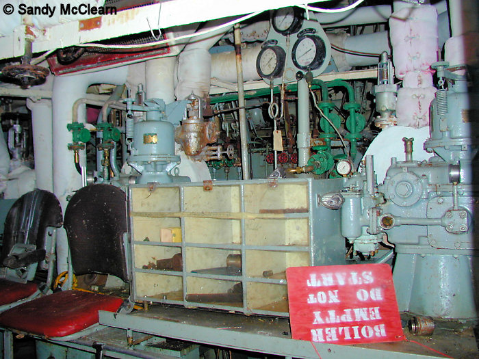
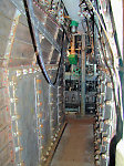
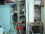
Boiler Room (TERRA NOVA)
|
2
|
|
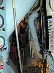
Looking aft?
along the port? side, over
the top of the port?
boiler.
|
3
|
|
|
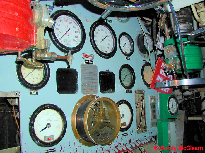
4
|
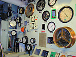
|
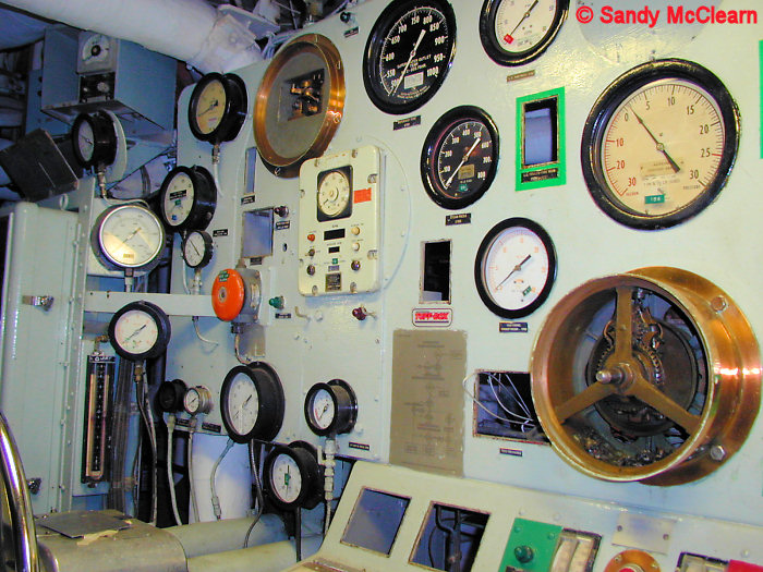
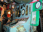
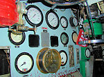
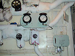
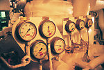
Looking forward and to port at the main boiler room
control panel.
The red and green on the left and right of this panel indicated,
respectively, the port and starboard boilers. The rows of red and green
lights on the nearly horizontal part of the panel (bottom left) are the
port and starboard boiler oil gun controls, respectively.
From Dave Holmes: "The
boiler room had two stokers, one
on each
boiler, two at the control panel and one manning the evaporators. One
of the guys on the control panel, usually an LS would control the
amount of oil guns that the stoker would insert and light off. He would
manually flick a toggle switch, and the light would come on. The stoker
would then insert and light off. You always had to keep an eye open to
see the lights going off and on, all done manually. If we needed more
steam, he would flick a couple of toggle switches and the stoker would
put the oil guns in service corresponding to the lights. The
guy who flicked the switches controlled the number of oil burners and
the oil pressure. The guy who sat behind him, controlled the FD fans,
and air flow to the boilers."
|
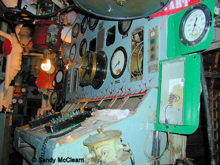
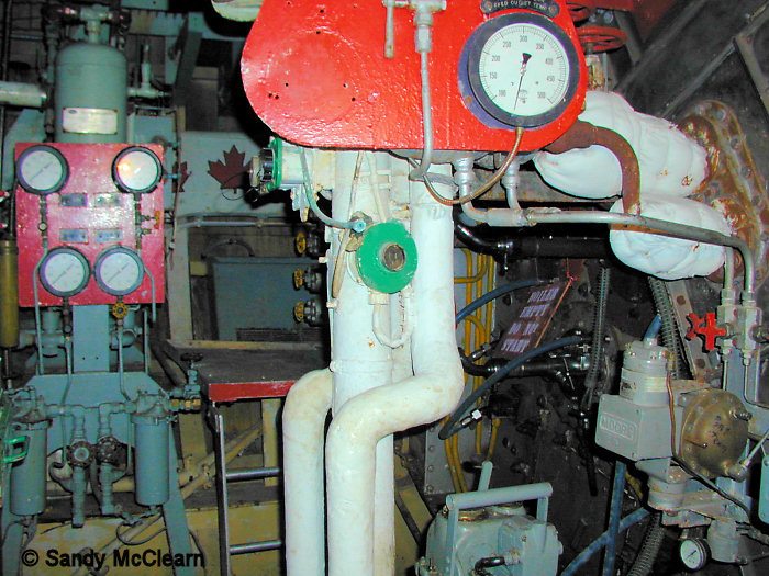
5
|

|
A piece of artwork painted during the 1991 Gulf War
deployment, based on the equipment shown.
|
6
|
|
|
7
|
|
|
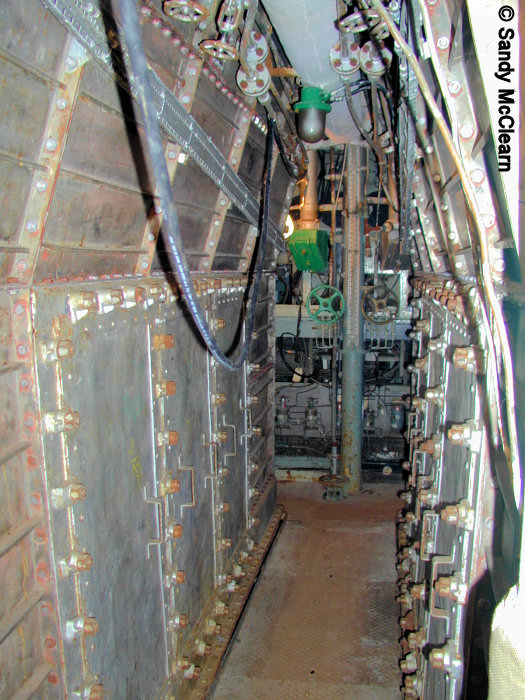
8
|
|
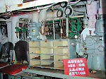
Looking between the two boilers.
|
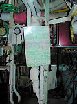
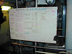
9
|
|
Boiler room status board.
|
10
|
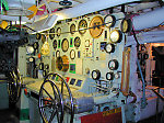
|
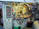
A close-up of the boiler room control panel.
|
Engine Room (TERRA NOVA and PLYMOUTH)
|
Items 11 to 25 cover the engine room in
ex-HMCS TERRA NOVA.
|
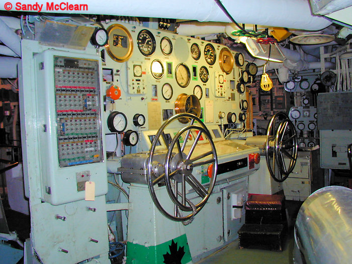
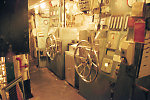
11
|
|
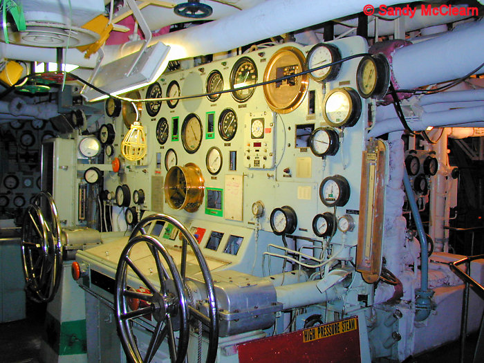
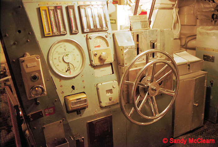
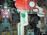
The throttle control station and control panel, looking
aft and to port. The big hand wheels were originally the common
throttles for the cruise and main
turbines (later just for the main turbines after the cruise turbines
were removed), port (right) and starboard (left), while the smaller
wheels
control the astern turbines. While standing at this control panel, you
would be facing aft. Compare this to the same station on PLYMOUTH in
Item #'s 42, 44, and 45. To the right of the photograph, in the
background, is the monitoring panel for the port side main circulation
pump.
From George Webster: "As an aside,
to the best of my recollection, the cruise turbine throttle was fitted
right on the front end of the engine which made it very difficult for a
throttle watch keeper to perform an astern movement as he would have to
close the cruise throttle then run back to the main console to open the
astern turbine throttle." |
12
|
|
The engine room status board, as it appeared on July
11, 1997, the date of TERRA NOVA's final sailpast in Halifax Harbour.
|
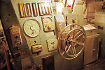
13
|
|
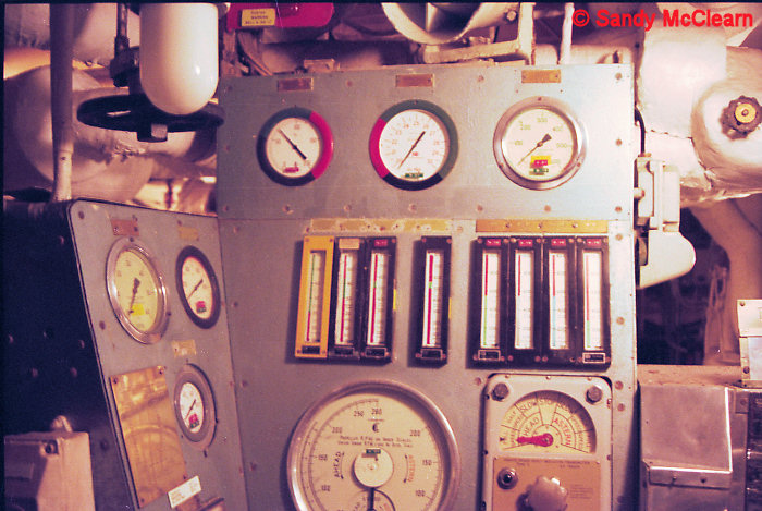
A close-up of the control panel, showing the readouts
for the starboard turbine.
|
14
|
|
The throttle control station looking aft and to
starboard.
|
15
|
|
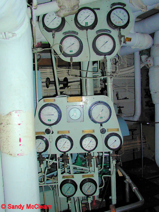
The monitoring panels for the starboard side main
circulation pump.
|
16
|
|
A view of the same monitoring panel shown in Item #29,
but from a different angle, possibly looking forward along the port
side.
|
17
|
|
Looking further down into the engine room.
|
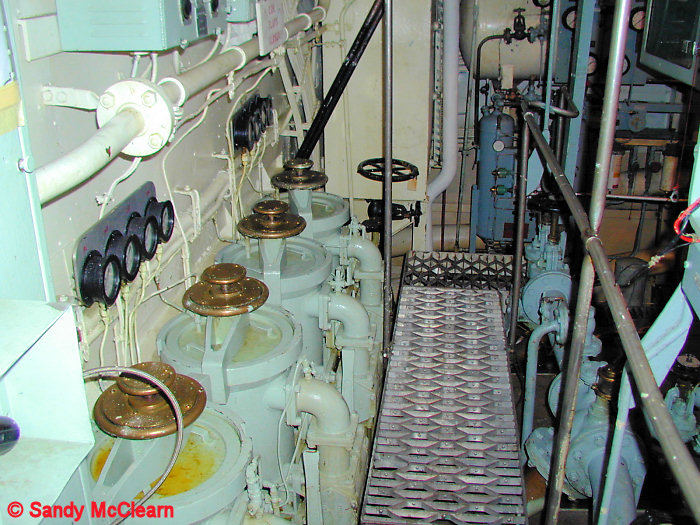
18
|
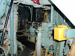
|
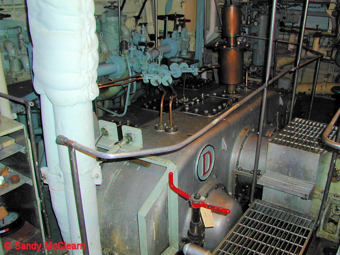
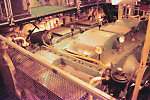
Looking aft and to port at the top of the port gearbox. The shaft in the
background comes from the main turbine, while the flat plate cover just
visible behind the main turbine shaft covers the opening intended for
the cruise turbine shaft. The rounded cover in the
foreground (under the "D") is over the quill shaft. Compare with the
port gearbox
in PLYMOUTH in Item # 47.
From George Webster: "In photo
number 32, the rounded cover is over the end of one of the quill shafts
in the main gearbox and the original cruise turbine entry point is the
flat cover which you can just see outboard over the very top of the
main shaft from the main engine turbines (ahead and astern)." |
19
|
|
Looking forward and to port at the top of the port
turbine.
|
20
|
|
|
21
|
|
|
22
|
|
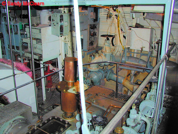
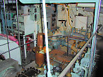
Looking forward and to starboard over top of the
starboard gearbox. It was the
starboard gearbox in KOOTENAY that blew up in October 1969, killing
nine crew members and injuring 53 others. |
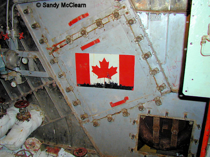
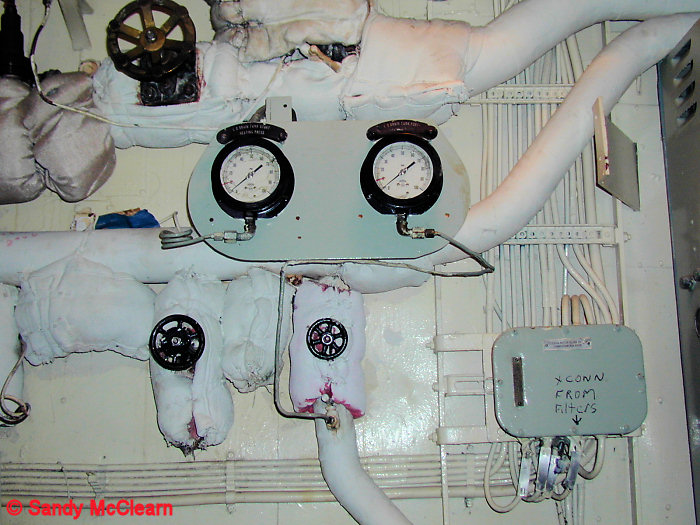
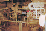
23
|
|
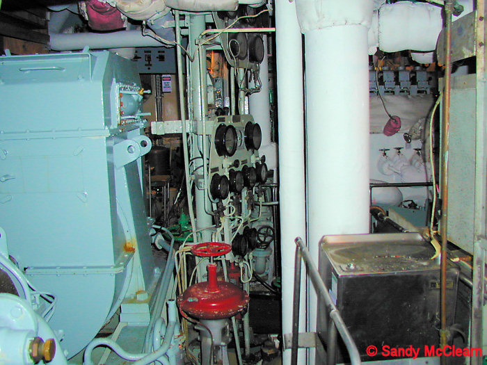
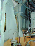
This is the aft bulkhead immediately behind the port
gearbox, looking to port (i.e. see background of Photo #32).
From George Webster:
"Photo 37 was taken from the centreline of the
platform which runs along the aft bulkhead of the engineroom and is
looking to Port. In the foreground are the main lubricating oil
filters for the turbines and main gearing. The filter covers used
to weep oil when the oil was cold as is apparent on the top of a couple
of filters." |
24
|
|
Looking forward and to starboard at the starboard
turbine.
|
25
|
|
Part of the bulkhead at the aft end of the engine room.
|
Items 26 to 34 cover the engine room in
ex-HMS PLYMOUTH.
|
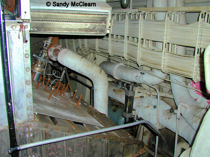
26
|
|
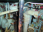
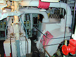
According to Ron
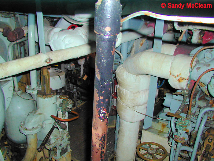
Monette, this shows the main steam line (top left) and a ventilation
trunk (top right, with vent).
|
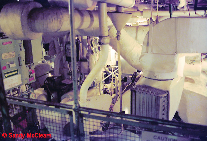
27
|
|
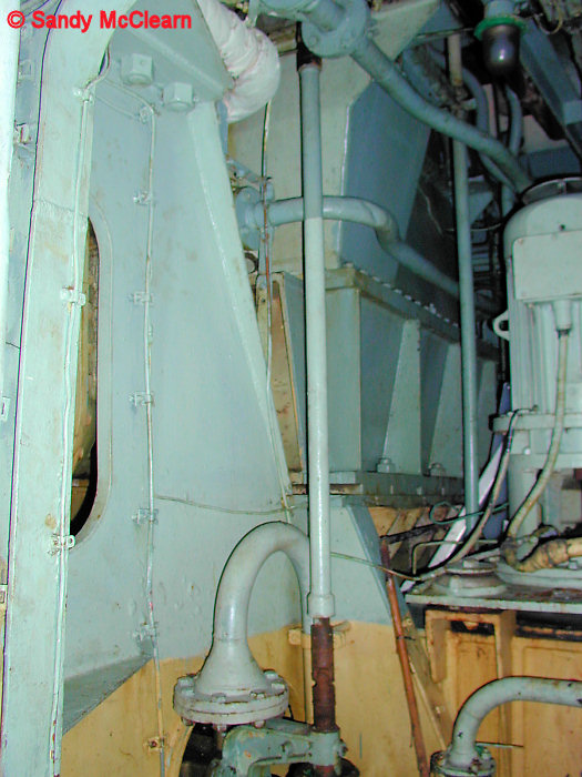
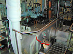
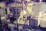
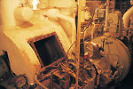
The port main turbine
(with white insulation covering) and the hydraulic pump for the port
active stabilizer can be seen to the left. The hydraulic pump sits
where the cruise turbine would have been formerly.
|
28
|
|
Looking aft and to
starboard at the throttle control station. Compare this to the same
station on TERRA NOVA in Item #'s 25, 27, and 28.
|
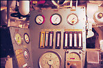
29
|
|
Possibly the engine room
turbo-generator, located at the starboard side at the forward end of
the engine room?
|
30
|
|
The starboard turbine
throttle control station looking aft.
|
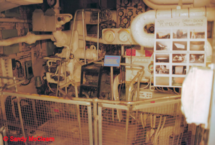
31
|
|
The starboard turbine
throttle control station looking aft. |
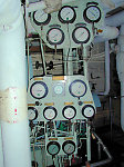
32
|
|
Monitoring panels.
|
33
|
|
The port gearbox,
possibly also
with a cover over the quill shaft (hard to tell from
this photo, unfortunately). Compare with the port gearbox in TERRA NOVA
in Item # 32.
|
34
|
|
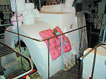
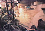
Starboard main turbine
with an inspection plate removed, exposing the turbine blades. The
starboard active stabilizer hydraulic pump is in the foreground.
|
TERRA NOVA diesel generator (genset or
gennie)
|
35
|
|
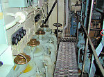
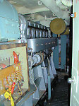
A diesel genset on
TERRA NOVA, looking aft into the compartment on the starboard side of
the ship.
|
Sources:
Barrie, Ron and Macpherson, Ken. (1996). Cadillac of
Destroyers: HMCS ST. LAURENT and Her Successors. Vanwell
Publishing
Ltd. St. Catherines, Ont.
Bowie, David. (2010). Cruising Turbines of the 'Y100'
Naval Propulsion Machinery. Unpublished article.
Steed, Roger G. (1999). Canadian
Warships Since 1956.
Vanwell Publishing Ltd. St. Catherines, ON.
RCN Publication. (1968). Machinery
Digest for Destroyer Escorts, 205, 206, 257 and Classes. Queen's
Printer and Controller of Stationary, Ottawa.
Conversation and correspondence with Jim Brewer, June 2006 to February
2007..
Conversations with Ron Monette, February and August 1999.
Correspondence with Dave Holmes, December 2006.
Correspondence with Dave Holmes, June 2007.
Correspondence with George Webster, December 2006 to February 2007.
|