1
|
|
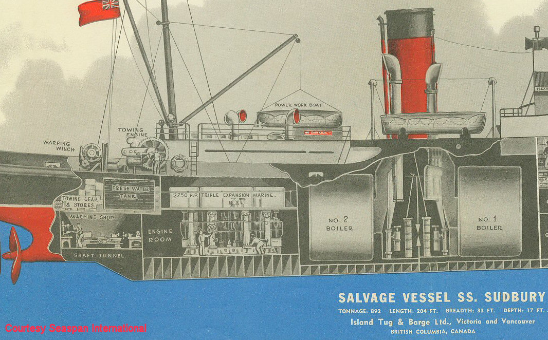
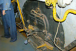
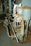
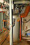
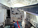
General
layout of machinery spaces in a Flower class corvette (actually ex-HMCS
SUDBURY after conversion to a salvage tug - image courtesy of
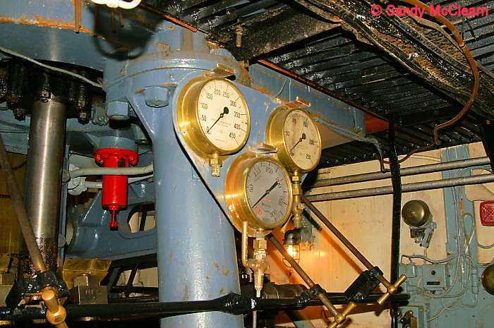
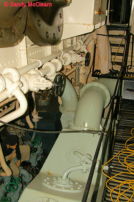
Seaspan International Ltd.). The 1939-1940
construction
program Flower class corvettes were fitted with two Scotch Marine
"fire-tube" boilers., as shown here. According to Corvettes of the Royal Canadian
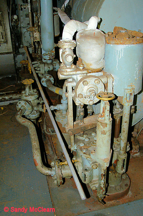
Navy, these boilers "...held the water inside the huge drum of
the boiler and the "fire" was shot through it in tubes which started in
the three fireboxes at the bottom and then snaked back and forth
through the drum."
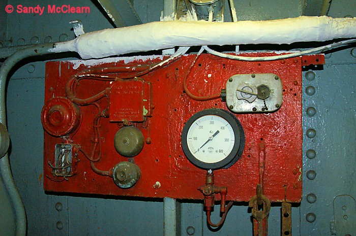
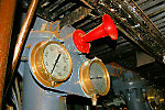
The large volume of water contained in these boilers
provided a large reserve of steam for hunting submarines, but meant
that the boilers were slow to raise steam from a cold start. In
addition, the Scotch Marine boilers turned out to be relatively
unreliable, and their size limited the supply of fuel that could be
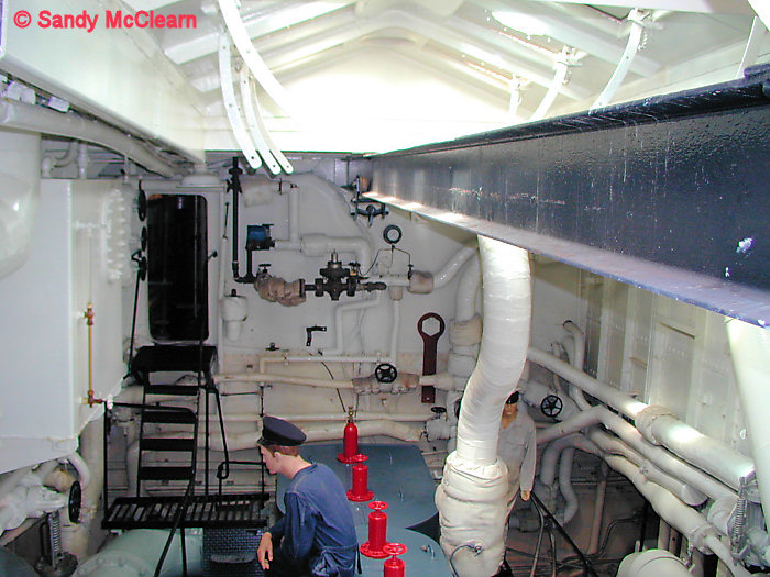
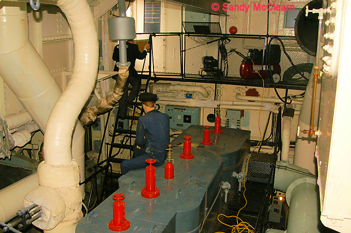
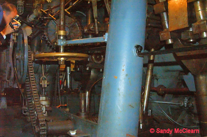
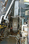
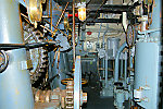
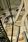
carried.
The 1940-41 construction program ships received "water-tube"
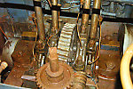
boilers instead, in which "...the main body of the boiler acted as a
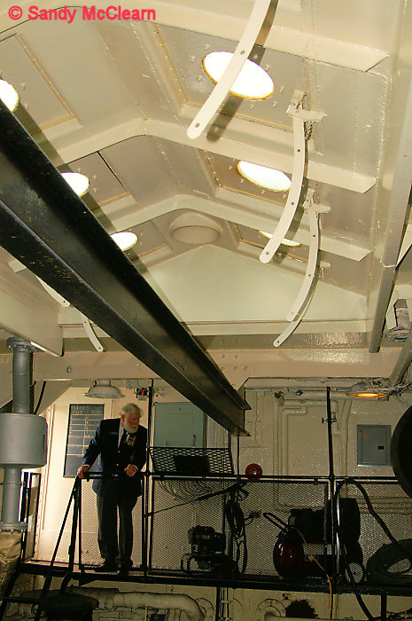
firebox and water passed through it in banks of tubes". These boilers
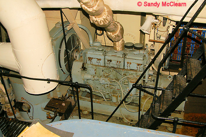
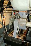
were superior in most respects to the Scotch Marine boilers that they
replaced, and later allowed for more fuel to be carried thus extending
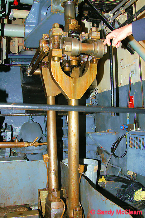
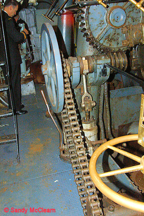
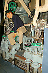
the range of the 1941-42 construction program onward.
The boilers provided steam to a four-cylinder triple expansion steam
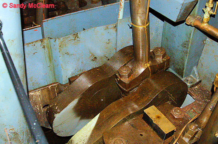
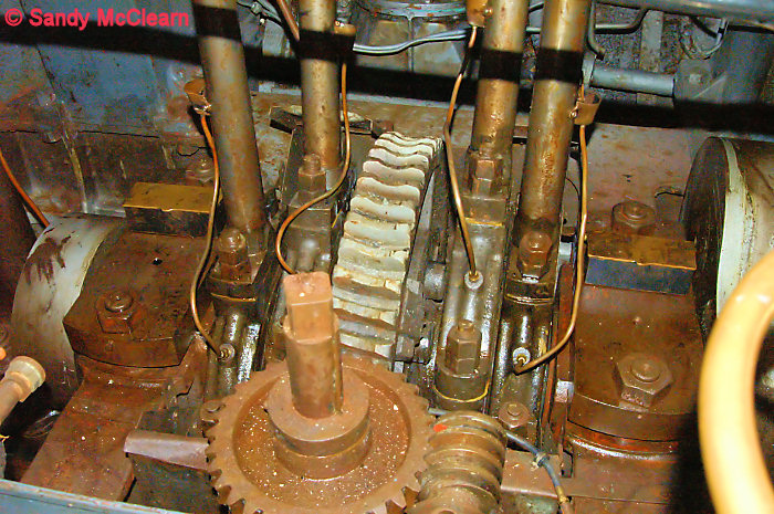
engine generating 2,750 horsepower, and providing a top speed of 16
knots..
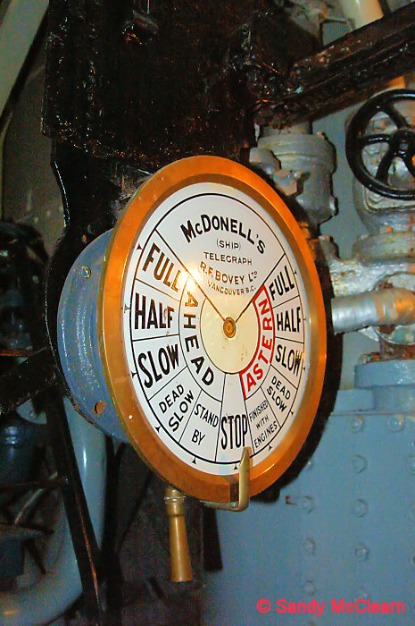
SACKVILLE herself had her #1 boiler removed during the war, a fact that
contributed to her survival into present day, as it provided space for
cable stores when she was converted into a controlled loop layer after
the war.
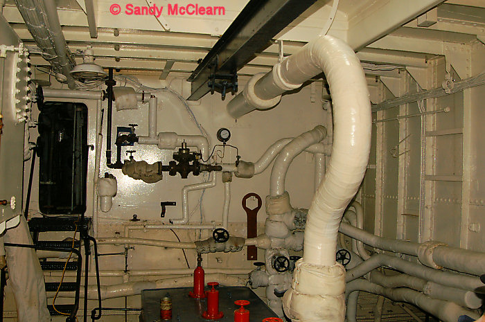
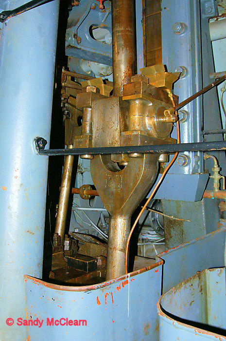
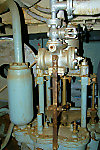
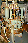
|
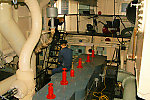
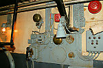
No.2 Boiler
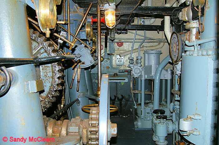
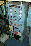
|
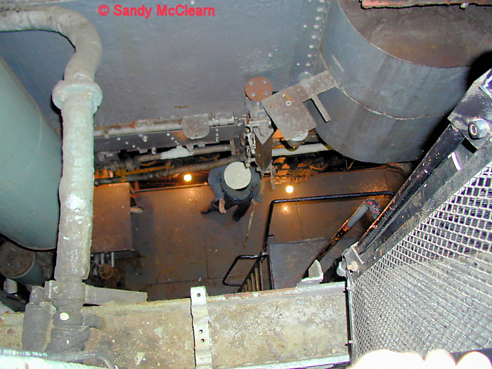
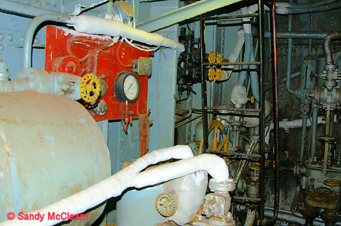
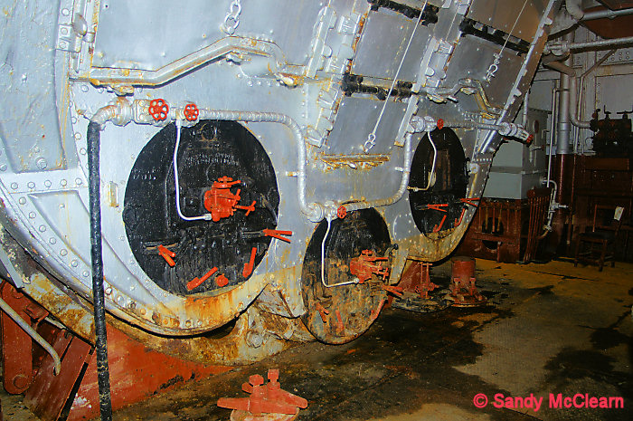
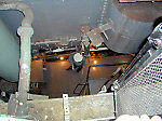
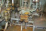
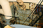
2
|
|
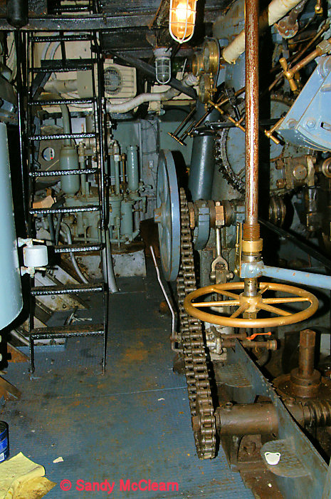
No.2 boiler room from above - looking down on the front
of No.2 boiler.
|
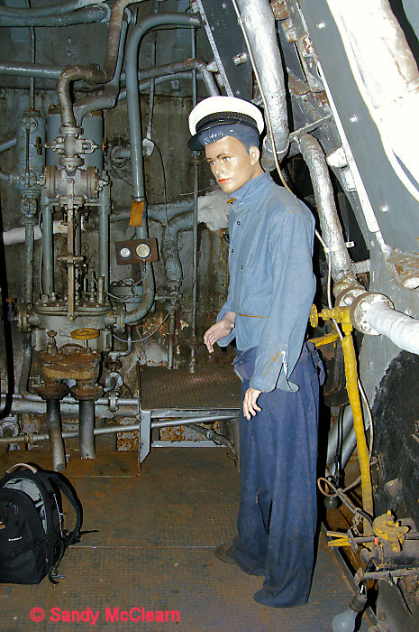
3
|
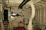
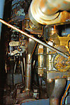
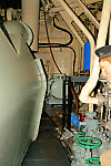
|
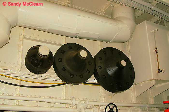
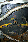
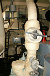
Looking to port. In the centre of the photo is the
forced air fan for combustion. To the left of the photo is the
starboard firebox of #2 boiler, one of three in the boiler.
|
4
|
|
Looking to starboard, with the boiler feed pump in the
background.
|
5
|
|
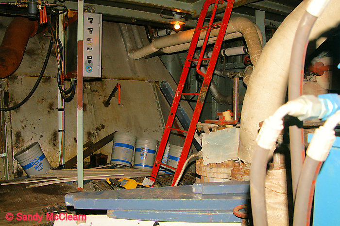
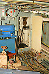
Looking to starboard, exit ladder leads out of boiler
room. The boiler room bilge pump is in the foreground.
|
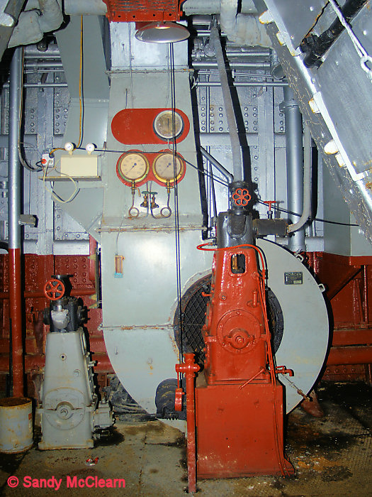
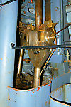
6
|
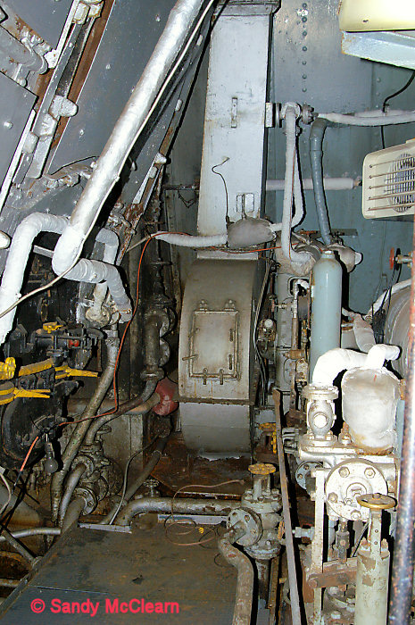
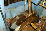
|
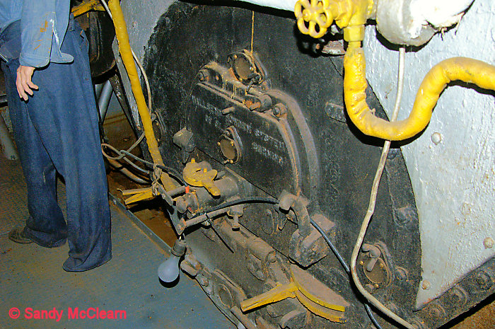
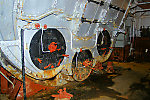
Front of No.2 boiler, showing the centre firebox.
|
7
|
|
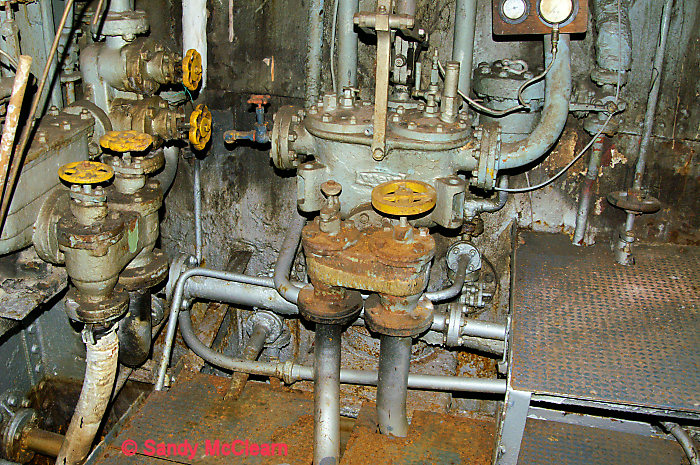
Starboard side.
|
8
|
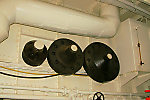
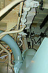
|
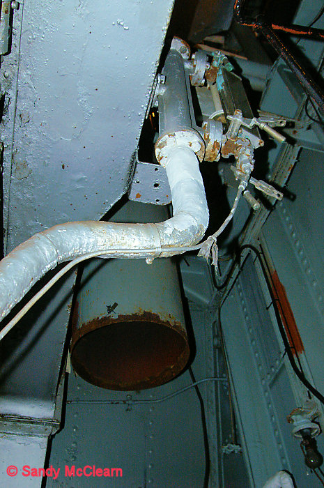
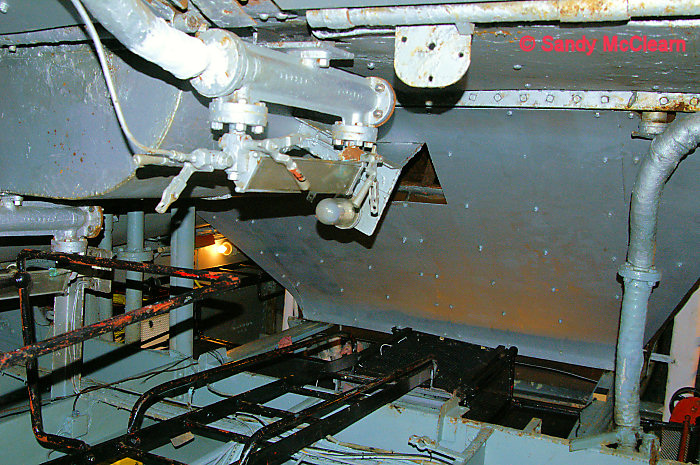
Pipe leading to starboard ventilator.
|
9
|
|
Mounted on forward bulkhead adjacent to exist ladder.
|
10
|
|
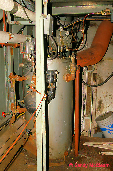
Starboard side. Fuel oil pump.
|
11
|
|
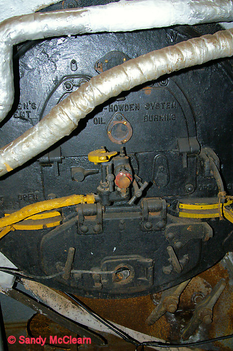
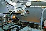
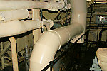
Fuel manifold on boiler front.
|
12
|
|
Looking up exit ladder towards trunking to funnel.
|
13
|
|
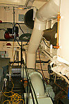
Looking forward to starboard in the space above No.2
boiler, with trunking to funnel in the background.
|
14
|
|
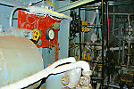
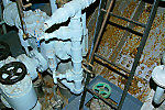
Space above No.2 boiler, forward port corner. Shows
current heating boiler 7 - 20 psi operation. |
15
|
|
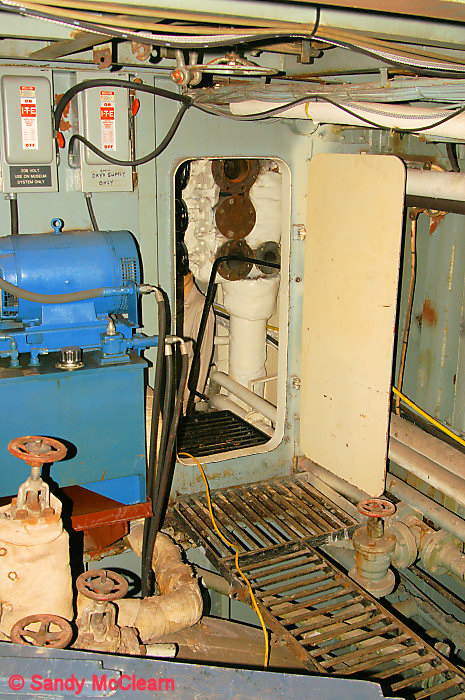
Space above No.2 boiler, looking aft on port side
through hatch to engine room. The equipment to the left of the photo is
part of the hydraulic package that is used to turn the main engine for
display purposes. This turns the crankshaft, which in turn moves the
connecting rods and pistons. This equipment is not original, and has
only been installed since SACKVILLE became a museum. |
16
|
|
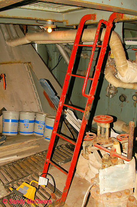
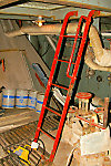
Ladder over No.2 boiler.
|
| 17 |
|
One of two similar
Scotch boilers installed in the Ernest
Lapointe at the Maritime Museum of Quebec, showing all three
fireboxes.
|
| 18 |

|
A side view of a forced
air fan similar to the one in Photo #3 above, also taken on board the Ernest Lapointe.
|
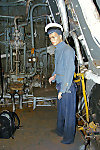
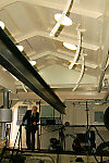
Engine Room
|
19
|
|
Looking forward in engine room, with hatch to space
above No.2 boiler on port side. Lifting beam runs fore and aft through
engine room over the engine.
|
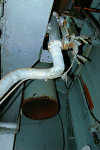
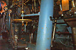
20
|
|
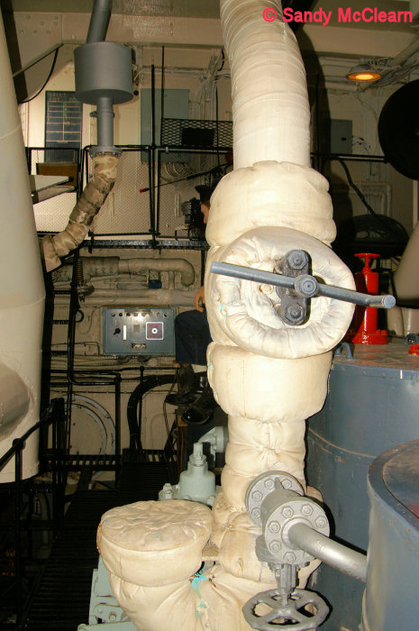
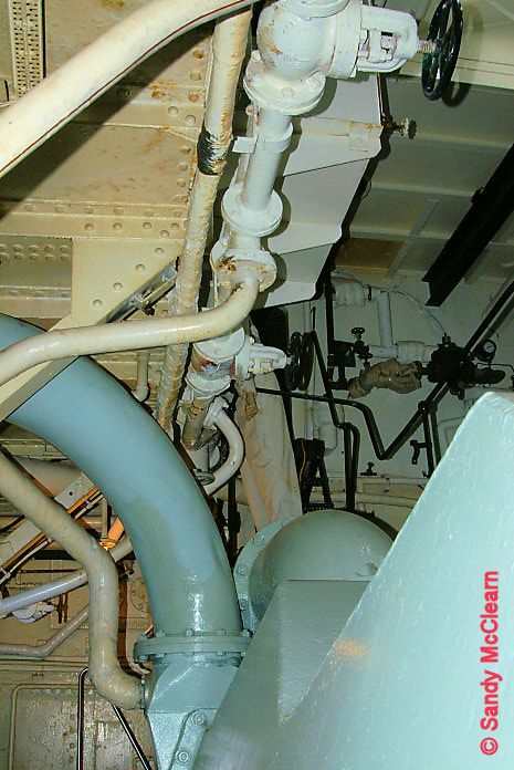
Looking forward in engine room. The curved piping seen
here is the "Aiton" bend in the main steam (supply) line from the the
main engine to the boiler that allowed for expansion in the line
and prevented stressing at the engine and steam throttle valve. |
21
|
|
Looking aft to starboard side in engine room. The grey
part in the middle of the photo is the top of main engine showing the
pressure relief valves and upper valve rod guides (the red objects).
The large diameter light grey pipe a the bottom right of the photo is
the exhaust steam line leading back to the condenser, which is
immediately to port of the main engine, but is just out of sight to the
bottom of this photo. |
22
|
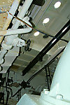
|
Looking aft and up in engine room. Port holes in deck
head visible.
|
23
|
|
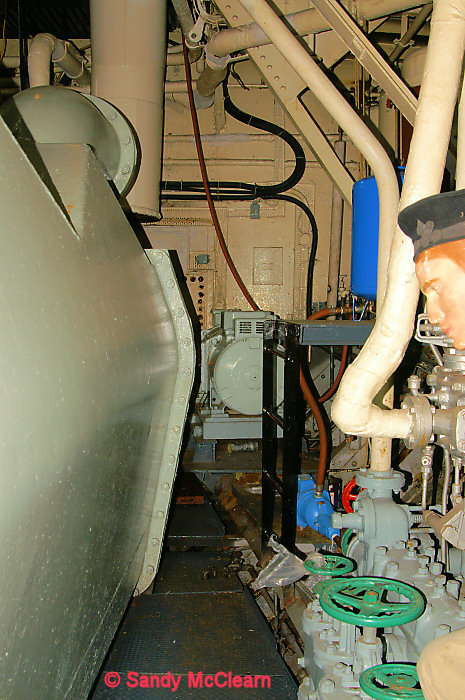
Diesel generator on starboard side of engine room, with
ventilation pipe to left. Radiator is to the left of the genset, with
the insulated exhaust leaving through the top centre of the photo.
|
24
|
|
Connecting rod between piston rod above and crankshaft
below at forward end of engine. The copper line running down the
connecting rod is a lube line.
|
25
|
|
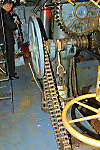
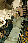
Looking aft along starboard side of engine, with
connecting rods in background. Shows reversing engine (the reversing
engine is a steam reciprocating engine utilizing a pinion
and gearwheel (rack) to swing the Stevenson Link gear to reverse
direction of rotation of the main engine), and also the handwheel
for the
throttle valve. Also shows the pinion and gearwheel (top
of photo). A rod from the gearwheel moves a lever on a longitudinalbeam
which moves all link gear as one. |
26
|
|
Forward connecting rods looking from starboard to port.
|
27
|
|
Looking aft above crankshaft.
|
28
|
|
Connecting rod attached to crank shaft.
|
29
|
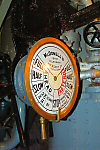
|
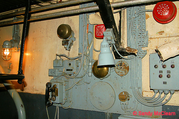
Engine room telegraph on starboard side of engine room.
|
30
|
|
Looking aft along starboard side. Shows the reversing
engine. Also
handwheel for throttle valve. |
31
|
|
|
32
|
|
Aft end of engine room, looking aft and port.
|
33
|
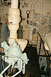
|
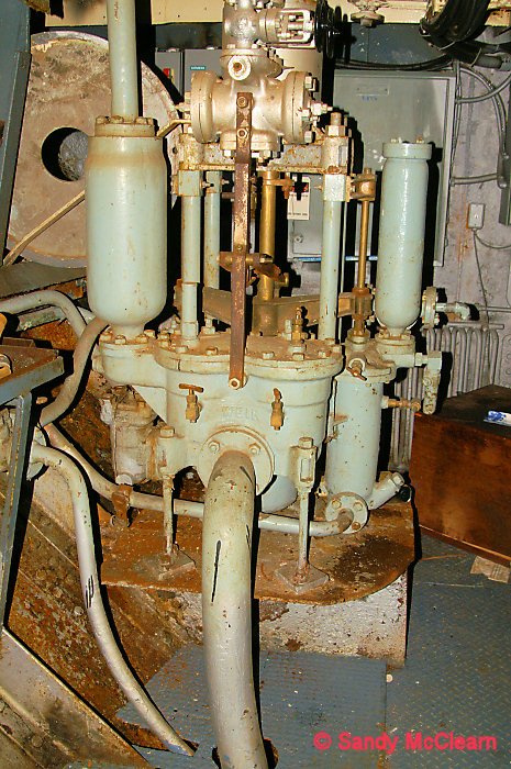
Three way pump for evaporator set (feed water, brine,
and distillate). |
34
|
|
Looking forward along
starboard side of engine room.
|
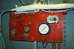
35
|
|
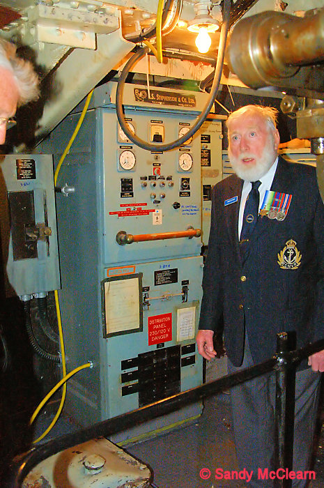
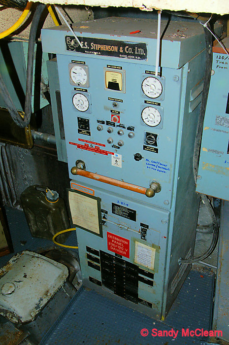
Electrical distribution
panel at aft end of engine room.
|
36
|
|
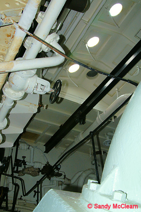
Looking aft and up to
deck head in engine room.
|
37
|
|
Starboard side, with
ship's hull visible to right of shot. This is the base of the engine
room feed pump. |
38
|
|
Looking aft along
starboard side.
|
39
|
|
Port side, looking aft.
Salt water service or bilge pumps. |
40
|
|
Shows the actuating arm
that swings to move the link gear. |
41
|
|
|
42
|
|
Three way pump again. |
43
|

|
Starboard side, looking
forward and to port.
|
44
|
|
Forward bulkhead.
|
45
|
|
Starboard side, looking
forward and up bulkhead.
|
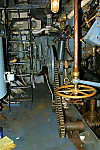
46
|
|
Starboard side, looking
forward along catwalk to bulkhead. Main steam chest and throttle valve.
|
47
|
|
A view of the main
engine pistons removed for display on the port side of the engine room.
|
48
|
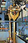
|
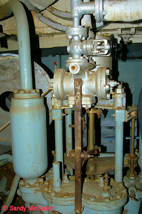
Starboard side, looking
aft. In the foreground is the main steam isolation valve, at the bottom
of the "Aiton" bend. |
49
|
|
Starboard side, looking
aft with ventilation piping visible.
|
50
|
|
Looking aft along the
port side. The light grey exhaust steam pipe exits the main engine and
enters the condenser (bottom centre). The condenser is cooled by sea
water, and condenses the steam from the engine to return it to the
boiler to be reused.
|
51
|
|
Looking down onto the
condenser, forward along the port side. The condenser is at the bottom
centre of the photo, and a pipe leaves the condenser to return water to
the
boiler via some feed pumps, a feed-water heater, and a deaerating tank.
|
| 52 |
|
Looking aft along the
port side, with the condenser to the left.
|
| 53 |
|
Looking forward along
the port side with the condenser to the bottom right. |